How to Read Electrical Symbols

Last updated August 12, 2024
Wiring diagrams and electrical schematics show how components connect in a circuit or electrical system. Standardized circuit diagram symbols represent these components visually so you can easily repair, troubleshoot or make additions to the circuits.
This guide reviews the major types of electrical symbols and the difference between wiring diagrams and schematics.
Difficulty:
Beginner
Duration:
Under 2 hours
Table of Contents
What Are the Basic Electrical Symbols?
What Are Some Symbols Used in an Electrical System Schematic?
What Is an Electrical Schematic?
More Tools. More Products. More Perks.
What Are the Basic Electrical Symbols?

These are the most basic electrical diagram symbols, which can represent simple circuits. Each component has its own symbol. In schematics, many components are also represented by a letter code, shown in parentheses below.
- Switches (S or SW) are electrical components that can connect or disconnect the conducting path in an electrical circuit. They also can change the path of the current flow. Symbols can indicate the difference between toggle or push-button switches and whether they are in the On or Off position.
- Resistors (R) restrict the flow of electrical current.
- Capacitors (C) store electrical charge and can be either polarized or non-polarized.
- Diodes (D) are polarized devices that allow electrical current to flow in only one direction.
- Light emitting diodes, or LEDs, are semiconducting light sources that emit light when current is flowing through them.
- Transistors (Q) are semiconductor devices used to switch or amplify electrical signals and power.
- Batteries (BT) are power sources that store electric charges and can generate constant voltage. Batteries consist of cells and have positive and negative poles.
What Are Some Symbols Used in an Electrical System Schematic?

These are some of the additional schematic symbols commonly used for electric systems.
- Wires are conductors of electrical current. Symbols represent connected and unconnected wires.
- Ground wires provide protection from electric shocks.
- Fuses (F) are designed to disconnect when current exceeds a set amount.
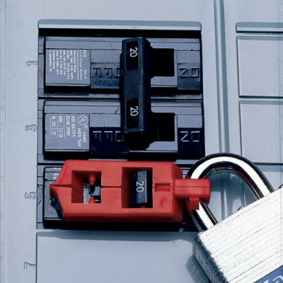
- Circuit breakers protect systems from excessive currents or short circuits by interrupting current flow.
- Inductors (L) are coils that generate magnetic fields.
- Transformers (T) transfer electricity from one circuit to another.
- Relays (K) are electromagnetic switches.
- Power sources supply circuits with electric power, which can come from batteries, electric outlets, generators and more.
- Electric bells ring during the application of electrical current.
- Buzzers emit a buzzing sound during the application of electrical current.
- Lamps generate light during the application of electrical current.
- Loudspeakers convert electrical signals to sound waves.
- Antennae transmit or receive radio waves.
- Generators are sources of mechanical voltage.
What Is an Electrical Schematic?

Electrical drawing symbols are used in both wiring diagrams and wiring schematics. Electrical diagrams and schematics visually represent electrical circuits in different ways.
- Wiring diagrams show the connections and physical layout of an electrical circuit or system. They use electrical symbols to show how wires connect and where fixtures or other components can be added to the system. For home builders, a wiring diagram can provide a shortcut to locating electrical outlets and light fixtures. Wiring diagrams often appear in owner’s manuals for electric devices.
- Wiring schematics show how electrical circuits work, but do not represent the physical layouts. Schematics show the circuit’s components in more detail than diagrams. Wiring schematics can be used for building circuits, manufacturing electronic devices or helping to ensure a system is up to code. Schematics tend to be used by qualified technicians.
Knowing how to read electrical symbols can help you identify types of components (resistors, inductors, capacitors, etc.) and their placement in a circuit. Electrical diagram symbols often use arrows to indicate the direction of current around a circuit or through a component.
Pro Tip: Most wiring diagrams and schematics use standardized electrical symbols. Some organizations, such as the International Electrochemical Commission (IEC) and the Institute of Electrical and Electronics Engineers (IEEE) use different symbols for some of the same components.
More Tools. More Products. More Perks.

Be more competitive and boost your bottom line with Pro Xtra, The Home Depot's loyalty program built for Pros. Sign up today to access the enhanced Pro Online Experience, built with the online business tools and time-saving features Pros need.
Authorize employee in-store purchases quickly and securely via text. When Pro Xtra members enroll in Text2Confirm, you have total visibility to a detailed list of everything your employee is buying.